


Please Leave Us A Message
Privacy statement: Your privacy is very important to Us. Our company promises not to disclose your personal information to any external company with out your explicit permission.

Jilin Lander Intelligent Technology Co., Ltd
 October 12, 2022
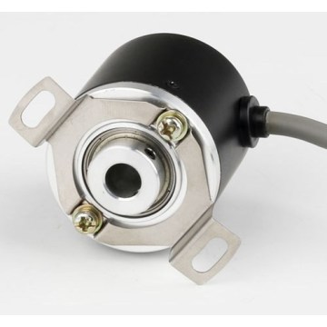
Optical Encoder Classification And Selection
The encoder Encoder is a kind of sensor, which is mainly used to detect the speed, position, angle, distance or count of mechanical motion. Except for industrial machinery, many Motor controls such as servo motor and BLDC servo motor The use of an encoder for the motor controller as a commutation, speed and position detection makes it a very versatile application. According to the detection principle, encoders can be classified into optical, magnetic, inductive and capacitive. According to its calibration method and signal output form, it is divided into Incremental Encoder and Absolute Encoder. Photoelectric encoders use the principle of grating diffraction to realize displacement-to-digital conversion. Since the 1950s, they have been used in machine tools and computing equipment. Because of their simple structure, high measurement accuracy, and long life, they are valued and promoted at home and abroad. Positioning, speed, length, acceleration, vibration, etc. are widely used.

When the incremental encoder shaft rotates, there is a corresponding pulse output, and the count starting point is arbitrarily set, which can realize infinite multi-turn accumulation and measurement. Rotation of the encoder shaft will output a fixed pulse. The number of pulses is determined by the number of encoder encoder lines. When you need to increase the resolution, you can double or replace the high-resolution encoder with two signals of A and B with a phase difference of 90 degrees.
Absolute encoders have code output corresponding to the position, usually binary code or BCD code. From the change in the size of the code, the position of the forward and reverse directions and the position of the displacement can be discriminated. The absolute zero code can also be used for power-off position memory. Absolute encoders typically measure 0-360 degrees.
Each revolution of the shaft, the incremental encoder provides a certain number of pulses. Periodic measurements or pulse counts per unit of time can be used to measure the speed of movement. If the number of pulses is accumulated after a reference point, the calculated value represents the rotation angle or stroke parameter. The difference between the two channel encoder output pulses is 90o. The electronic device that receives the pulse can receive the rotation sensing signal of the shaft, so it can be used to achieve bidirectional positioning control; in addition, the three-channel incremental rotary encoder generates a pulse called a zero signal per cycle.

Incremental Absolute Rotary Encoders The absolute encoders provide a unique encoded digital value for each axis position. Especially in positioning control applications, absolute encoders reduce the computing tasks of the electronic receiving device, eliminating the need for complex and expensive input devices: Also, when the machine is turned on or the power supply fails, the power is turned on. Need to return to the position reference point, you can use the current position value.
The single-turn absolute encoder subdivides the axis into the specified number of measuring steps. The maximum resolution is 13 bits, which means that the maximum 8192 position can be distinguished + the multi-turn absolute encoder can not only measure the angle in one revolution. Displacement, and fortunately, J uses multiple gears to measure the number of turns. The number of laps in multiple laps is 12 bits, which means that up to 4096 laps can be identified. The total resolution can reach 25 or 33,554,432 measurement steps. The parallel absolute rotary encoder transmits the position value to the evaluation electronics in parallel via several cables.
The rotary incremental encoder outputs pulses as it rotates, and its position is calculated by the counting device. When the encoder is not moving or is powered off, the internal memory of the counting device is used to remember the position. In this way, when the power is cut off, the encoder cannot have any movement. When the caller is working, the pulse output of the encoder can not be interfered with and the pulse is lost. Otherwise, the zero point calculated and memorized by the counting device will be shifted, and this There is no way to know the amount of offset, and only the wrong result can be known.
The solution is to increase the reference point, and each time the encoder passes the reference point, the reference position is corrected into the memory position of the counting device. Before the reference point, the accuracy of the location cannot be guaranteed. In the industrial control, there are methods such as finding a reference point for each operation and starting the change.
This method is cumbersome for some industrial control projects, and even does not allow the boot change (to know the exact position after boot), there are some conditions do not allow the use of interference caused by the position error, so there is an absolute encoder The emergence of.
Absolute value rotary encoder has a lot of optical channel reticle on the optical code disc, and each reticle line has 2 lines, 4 lines, 8 lines and 16 lines. . . . . . Orchestration, so that at each position of the encoder, by reading the pass and dark of each reticle, we obtain a set of unique binary codes (from 2 to the power of n to the power of 2). Code), this is called an n-bit absolute encoder. Such an encoder is determined by the mechanical position of the photoelectric encoder. It is not affected by power failure or interference. Since each position of the absolute encoder determined by the mechanical position is unique, it needs no memory and no reference point. And do not always count, when you need to know the location, when to read its location. In this way, the encoder's anti-interference characteristics and data reliability are greatly improved.
The single-turn absolute encoder measures each track of the photoelectric encoder in rotation to obtain the unique code. When the rotation exceeds 360 degrees, the code is returned to the original point, which is inconsistent with the only principle of absolute coding. The encoder can only be used for measurements within a 360-degree range of rotation, known as a single-turn absolute encoder. To measure more than 360 degrees of rotation, a multi-turn absolute encoder is used.
Encoder manufacturers use the principle of watch gear machinery. When the center code wheel rotates, another set of code wheels (or multiple sets of gears, multiple sets of code plates) is transmitted through the gear, and the number of turns is increased on the basis of the single-turn code. Encoded to extend the measuring range of the encoder. Such an absolute encoder is called a multi-turn absolute encoder. It is also unique in that each position code is unique and does not require memory.
Another advantage of multi-turn encoders is that due to the large measuring range, the actual use is often more plentiful. This eliminates the need for rigorous changeover during installation, and allows one intermediate position to be used as a starting point, which greatly simplifies the difficulty of installation and commissioning.
The above is the Optical Encoder Classification And Selection we have listed for you. You can submit the following form to obtain more industry information we provide for you.
You can visit our website or contact us, and we will provide the latest consultation and solutions
Send Inquiry
Most Popular
lastest New
Related Products
Send Inquiry
Privacy statement: Your privacy is very important to Us. Our company promises not to disclose your personal information to any external company with out your explicit permission.
Fill in more information so that we can get in touch with you faster
Privacy statement: Your privacy is very important to Us. Our company promises not to disclose your personal information to any external company with out your explicit permission.